 Loading... Please wait...
5623551265
Categories
- Cases/Accessories
- Mobile Accessories
- Coolers/Fans
- MultiMedia
- Notebook Accessories
- PC Components
- Specials
- Home
- Coolers/Fans
- Accessories
- Fan Cables
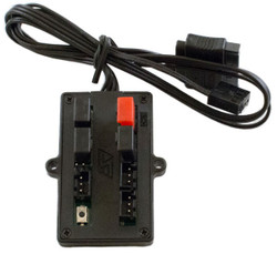
- Swiftech IRIS-ECO ALED Light Controller/PWM Hub
Swiftech IRIS-ECO ALED Light Controller/PWM Hub
Price:
$13.79
MPN:
IRIS-ECO
Brand:
UPC:
877790003135
Condition:
NEW
Availability: Ships in 2 business days
.
Shipping:
Calculated at checkout
Sorry but this item is currently unavailable.
Please check back at a later stage.
Product Description
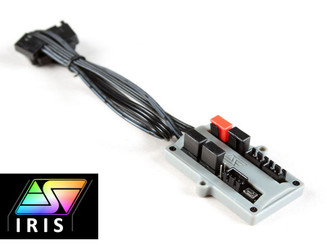
This multi-function ALED light controller and PWM hub operates as follows:
- Light control chip on-board, allowing to change the color and intensity of Addressable type RGB LED's (ALED) - the chip provides 8 color choices + 3 dimming settings; the PCB is populated with three 3-pin ALED connectors, 1 push-button switch for light control, and one 2-pin connector for remote light control: by using the "reset" connector of your case control panel for example, you can change the lighting scheme of your entire system from the chassis reset button.
- PWM hub function: the PCB is populated with four 4-pin fan connectors providing control of up to four PWM devices (fans and/or pumps) from a single PWM fan connector on the motherboard - we recommend using the CPU_fan connector for that purpose. This allows users to control the speed of all the connected PWM devices concurrently. The PWM signal from the motherboard CPU_fan controls the speed of the devices as a percentage of their maximum speed. For example, if you have a pump with a maximum speed of 3,000 RPM's, and 3 fans with a maximum speed of 1,000 RPM's connected to the hub, and if you set the CPU fan speed to 50% in your BIOS, then all devices will run at 50% of their maximum speed, i.e. the pump will run at 1500 RPM's, and the fans will run at 500 RPM's (please note that various PWM compatible devices may have different ramp-up speed curves, so these percentage will not necessarily result in the exact speeds described here).
Device speed: out of the four connectors on the PCB, one is identified by a Red Cap, and a "CH1" marking : this is the PWM master connector. In effect, since only one RPM signal can be read by one motherboard connector, only channel 1 of the PWM hub carries an RPM signal; thus the motherboard will only read the RPM signal of the PWM device that is connected to channel 1. For example, if you connect the pump to CH1, and it has a 3,000 RPM maximum speed, then the motherboard will read up to 3,000 RPM for the pump speed, even if fans with a lower maximum speed are connected to the hub. Conversely, if you connect a fan with a 1000 RPM maximum speed to CH1, and a 3000 RPM pump to one of the other connectors, the speed detected by the Motherboard will only be that of the 1000 RPM fan.
- Power to the IRIS controller is supplied by a SATA connector that must be connected to the Power supply for the fans to work. Regarding pumps, please note that due to the maximum power limitations allowed by 4-pin fan connectors, Swiftech pumps feature two connectors: one for power (either SATA or Molex 4-pin) and one for the PWM/RPM signal. When using a PWM hub to control the pump speed, the pump power connector must also be connected to the power supply for the pump to work.
Important note: the Skulls depicted in the above schematics symbolize the fact that users should NEVER attempt to connect the 3-pin female ALED connectors found in Swiftech's accessories (waterblocks, kits, etc..) to the male 4-pin fan connectors found on the Iris-Eco controller or anywhere else on the motherboard; in effect, this type of component uses 5v current whereas fan connectors use 12v current, and doing so would result in permanent damage to the LED's.
Specifications summary:
- Junction housing including: (4) Male 4-pin connectors, (3) Male 3-pin ALED connectors, (1) 2-pin connector, (1) ALED controller with push-button switch
- (1) Female 4-pin mini-connector to be plugged into Motherboard CPU_FAN connector
- (1) Male SATA connector to be connected to the power supply
- Peel-off sticker
- Mounting screws
- RoHS compliant
Other Details
MPN:
IRIS-ECO



 Our newsletter